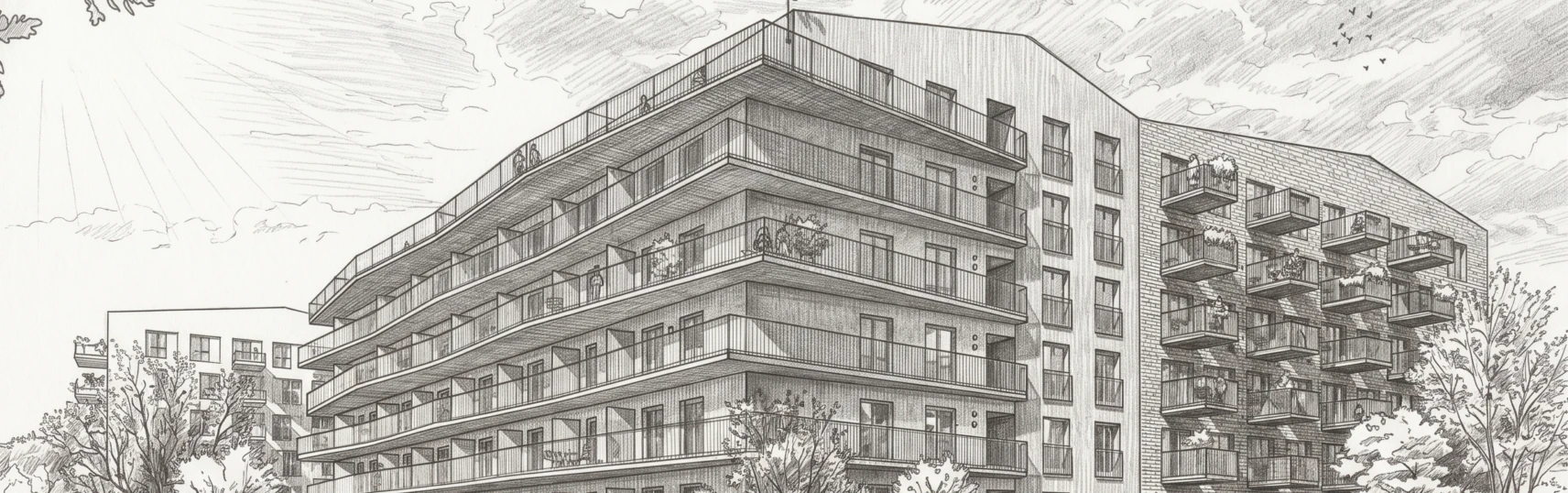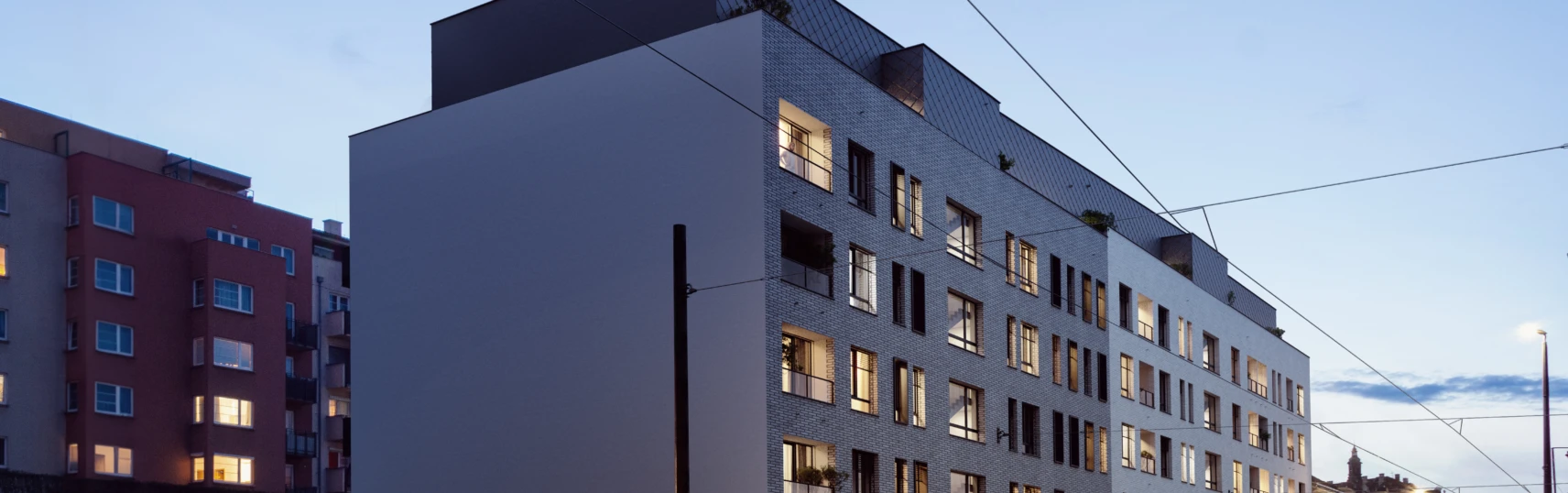
The foundation of the Karolina Plazza 1 residential complex in Prague 8 – Karlín.
Karlín in Prague has long been a very attractive area for the construction of residential and office buildings. We have reported in detail on the foundations of many of them in our magazine, most recently in issue 1/2015 in the article on the Meteor D multifunctional building in Prague 8 – Karlín. Although suitable sites for new construction in Prague, and therefore in Karlín, are generally disappearing fast, fairly attractive plots can still be found. One such plot is the one on which the Karolina Plazza complex is now being built, situated between Sokolovská and Křižíkova Streets. The excavation pit itself was secured with diaphragm walls; the monolithic structure was founded on piles from the level of the 2nd basement, where a bracing floor slab was built at the same time, beneath which excavation of the lower floors and construction of the foundation slab continued. The method of securing the substructure in this design was highly sophisticated, and all the structures were closely interconnected.
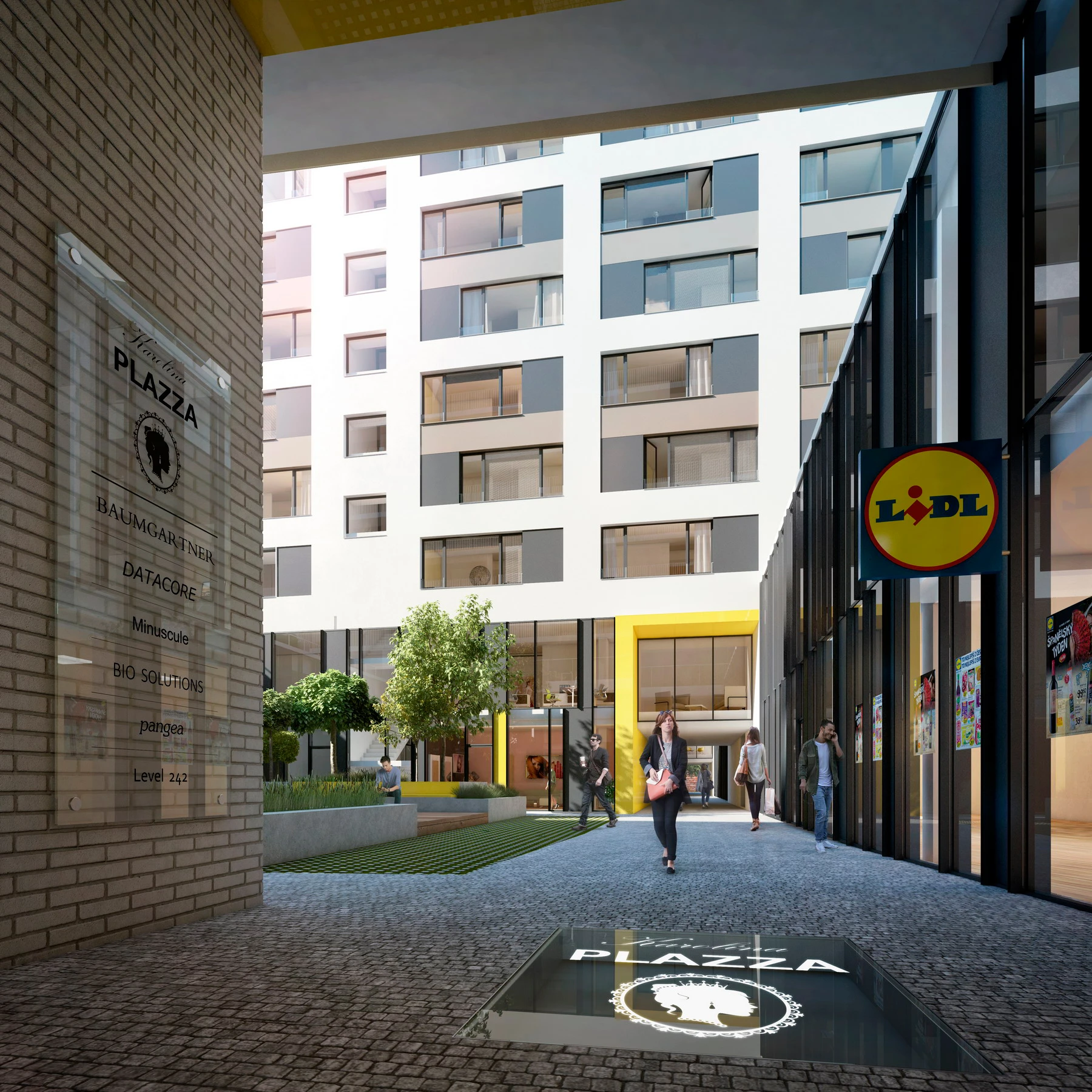
In the original built-up area of Karlín, in a gap site between Sokolovská and Křižíkova Streets, the new Karolina Plazza residential complex is taking shape. Three blocks of 8–9 floors above ground will hold around 150 apartments in studio to four-room layouts. The first floor of the buildings will have a through arcade with retail premises, the second floor will serve as offices, and from the third floor upwards there will be residential apartments. The underground part of the complex is shared by all the blocks and has three floors. A Lidl store will be located on the first basement level; the remaining floors will be used mainly for parking and cellars. The excavation pit for the building’s underground floors has a perimeter of around 280 m and a plan area of 3,621 m². The excavation depth is around 11 m. Construction began in January 2016 and completion is planned for March 2018.
Geological conditions (simplified)
– 0–3 (4) m below ground level … made ground;
– 3.0–4.5 m … sands S3;
– 4.5–11.5 m … gravels G3;
– 11.5–12.5 m … weathered shale R5;
– 12.5 m and below … slightly weathered shale R4;
– Groundwater was encountered around 4.8 m below ground level.
Structural scheme – construction sequence
First, the sequence of construction of the substructure up to the level of the floor above the 2nd basement, in brief:
- Securing the excavation – structural diaphragm wall.
- From the working level of the 2nd basement floor slab, piled foundation of the monolithic structure and installation of temporary steel columns in the piles to support the 2nd basement floor slab.
- Construction of the floor slab above the 2nd basement (–4.20 and –4.35 m), which serves as the main bracing system. Openings were left in the slab at the cores and ramps for the removal of excavated soil and the supply of building materials.
- Excavation of the pit to the final excavation level.
- Construction of the foundation slab.
- Construction of the floor slab above the 3rd basement, including the associated columns, walls and cores from the foundation slab up to the 2nd basement floor slab.
- Concreting of the openings left in the floor slab above the 2nd basement (including the associated columns, walls and cores).
The rest of the construction then proceeds in the standard way, floor by floor upwards.
Archaeological survey
Earthworks in the pit were carried out under archaeological supervision. Along Sokolovská Street, cellars built in the second half of the 19th century were examined, and further cellars were uncovered in part of the remaining area. Three wells were also discovered and documented, two probably from the 19th century and the third even older. The oldest and most valuable finds were the remains of five kilns, probably brick kilns, spread evenly across the site – originally most likely a single production area. One of the kilns is unique in having survived in its entirety, including its stoking pit. These production structures probably date from the 18th century, but may be even older.
Securing the excavation pit
The pit is supported by an 800 mm thick structural diaphragm wall (DW), which also serves as the wall of the underground floors. Before the diaphragm wall could be built in the immediate vicinity of the existing buildings, the area had to be prepared. The main task was to remove obstacles to the excavation of the DW – chiefly the remains of cellar structures from the former buildings. The existing ground was carefully excavated in strips around 1.5 m wide down to the level set by the design. The surface of the masonry of the neighbouring buildings was cleaned by hand and then covered with 50–150 mm of shotcrete reinforced with one layer of 100/6 mesh. As part of the preparatory work, the former nursery school building was demolished. Its foundations were then excavated in strips around 1.2 m wide and immediately filled with P60 cement screed. Guide walls had to be built for the construction of the diaphragm walls; the design specified reinforced concrete walls 1.0 and 1.5 m high
with a clear width of 850 mm. The vertical joints in the panel interlocks were sealed with a soft PVC profile and supplemented with a sleeve-port injection pipe on the water side. Grouting was carried out no sooner than 7 days after the panels were concreted. The stability of the excavated diaphragm wall trench was ensured by the hydrostatic pressure of bentonite slurry. The wall toe level given in the design documentation was binding for the final structurally required depth of the panels. A further essential condition was that the diaphragm walls be embedded in the layers of weathered to slightly weathered shale of class R4 to a depth of ≥ 1.0 m. Concreting of the panels began immediately after the support slurry had been cleaned and the reinforcement placed. In accordance with ČSN EN 206 and 1538, concrete C 25/30 XA1, Cl 0.2, Dmax 22, S4 was specified. The reinforcement of the DW80 consists of welded cages of B500 B steel. Central placement of the cages in the trench and the required cover were achieved with spacer wheels and spacer bars. The cover to the face of the horizontal reinforcement is 80 mm. A Liebherr HS 855 cable crane with a Stein K810 grab measuring 2.8 × 0.8 m was used to excavate the diaphragm walls. The face of the DW80 was progressively trimmed by milling as excavation proceeded. The milling quality was specified such that irregularities on the DW surface were not to exceed 30 mm over a 2.0 m straightedge. The watertightness of the diaphragm wall was specified as class A2 in accordance with the Austrian Concrete Association’s Guideline on Watertight Diaphragm Walls of 11/1999. Only at the ramp, which was used for excavation and the removal of soil, was the diaphragm wall anchored (struts would have been in the way here). Temporary strand anchors were used (6 × Lp Ø 15.7 mm, steel 1570/1770 MPa). A mix of c : w = 2.2 : 1 (cement CEM II/B-S 32.5 R, density 1.87 kg/l) was used for grouting and high-pressure injection of the anchors. Drilling through the DW80 was carried out into Ø 219/6.3 sleeves with a 350 × 350 × 10 mm plate.
Foundation options depending on groundwater uplift
Because the building’s foundation level lies around 6–7 m below the groundwater table, earlier stages of the design proposed founding the building on an 850 mm thick foundation slab supported by large-diameter piles. The slab had to be designed for water uplift, which also led to the design of tension anchors in the areas outside the complex’s “towers”. During the design work, an option with a foundation slab not loaded by water uplift at all was also cautiously examined. This would mean that the inflow of water into the space bounded by the diaphragm walls and the surface of the bedrock would have to be very small, and therefore easy to pump. A further question was how to “dispose of” the pumped water. A technical solution of this kind is certainly not common in the given hydrogeological conditions. Nevertheless, the idea was so attractive for its many advantages that it was decided to carry out a theoretical hydraulic calculation and then a long-term pumping test. Three pumping wells inside the building and two infiltration wells on the south side outside the building were provisionally designed. The theoretical calculation was commissioned from Aquatest, a. s. The main task was to determine the rise in the groundwater table at the basements of the existing buildings adjoining the infiltration wells. Under normal conditions the groundwater table is ≥ 1 m below the foundation level of the buildings. The MODFLOW flow model (Harbaugh and McDonald 2000) was used to calculate the groundwater table. MODFLOW is a 3D model based on the finite-difference method. The calculations also allowed for the construction of the future neighbouring building, Karolina Plazza 2. The calculation yielded the following findings: – With infiltration of 1 l/s, the groundwater table beneath the foundation level of the affected buildings rises by 20 cm.
With infiltration of 1 l/s plus the construction of the future Karolina Plazza 2 building, the groundwater table beneath the foundation level of the affected buildings rises by 30 cm. Theoretically it was calculated that a total inflow of ≈ 1 l/s would be perfectly acceptable.
Pumping and infiltration tests were then carried out. The overall foundation concept was to be designed on the basis of their results: A. If the water inflows matched the assumptions, permanent pumping was envisaged. The pumped water would be discharged into the infiltration wells. The foundation slab would then be around 300 mm thick and would not be designed for water uplift. B. If the water inflows were greater than assumed, water would be pumped only for the duration of construction of the load-bearing structure up to the ± 0.0 m level. The foundation slab would then be around 850 mm thick and designed for water uplift. The slab would also be locally anchored with permanent bar anchors.
Three bored pumping wells were designed inside the building, in positions coordinated with the building’s architect. The 1,180 mm diameter bores were embedded around 6 m into the bedrock. The wells were lined with Ø 400/15.3 mm PE pipes, perforated in the sections 1.0–2.5 m and 4.0–6.0 m from the bottom. The backfill was 4–8 mm pea gravel. After the tests, the wells were shortened as excavation progressed and used to lower the water table in the pit. In the final stage they will be incorporated into pumping shafts and used for permanent pumping. To limit silting of these wells, the static groundwater reserve in the pit was pumped out through a temporary bored well. Outside the building, on the south side, two bored infiltration wells were designed in positions coordinated with the building’s architect. The 1,180 mm diameter bores rested on the bedrock. The wells were lined with Ø 400/15.3 mm PE pipes, perforated in the section 1.5–7.5 m from the bottom. The backfill was 4–8 mm pea gravel. After the tests, the wells were to be used to infiltrate the water pumped from beneath the building’s foundations. Before the pumping tests were carried out, the securing of the pit with diaphragm walls was fully completed. Some problematic joints between panels were sealed preventively by jet grouting. The long-term hydrodynamic tests themselves (pumping and infiltration) were commissioned from Glaukos, s. r. o. Only the conclusions are quoted here: The pumping tests were concluded at a pumped rate of 0.50 l/s (PW1: 0.08 l/s; PW2: 0.24 l/s; PW3: 0.18 l/s). The pumped rate was still falling; a steady state had not yet been reached. In the steady state the inflow will be in the range of 0.2 to 0.3 l/s. During the infiltration tests it was found that the infiltration structures (even individually) can easily accommodate the pumped volume from all the pumping structures. It can therefore be stated that the intended permanent inflow will have no significant effect on the local hydrogeological conditions and therefore cannot endanger the foundation elements of the neighbouring buildings.
On the basis of the results of the hydrodynamic tests, it was decided to implement option A, i.e. a 300 mm thick foundation slab without allowance for water uplift. Clearly, quite apart from the economic aspect, this solution greatly simplifies the problem of connecting the foundation structures to the DW.
Piled foundation
System bored piles of Ø 880 and 1,180 mm were designed for the building’s foundation. The piles were constructed from a working level of around –4.5 m. The lengths of the concrete pile shafts range from 4 to 10 m, with blank drilling of around 6–7 m. Given the geology encountered, the bores were cased exclusively with double-walled steel casings. In the layers of slightly weathered shale, drilling could continue without casing. High-quality rock augers had to be used to achieve the specified embedment. The piles were concreted using tremie pipes reaching above the bottom of the bore. In accordance with ČSN EN 206-1 and 1536, concrete C 25/30-XA1-Dmax 22-Cl 0.2-S4 was specified. Given the length of the blank drilling, the pile heads were over-concreted by around 0.5 m above the clean-concrete level. Bored piles of Ø 630 mm were designed for the temporary support of the 2nd basement floor slab. The piles were bored from a working level of around –4.5 m. The concrete pile shafts are 4 m long and the blank drilling is around 6 m. Given the geology encountered, the bores were cased exclusively with double-walled steel casings. Concrete of the same composition as for the system piles was specified. Steel columns of 2 × U300 (steel S 355) were set into the fresh concrete. A total of 121 piles with 1,568 m of bores and 77 supports with 753 m of bores were constructed on site. All large-diameter drilling was carried out with a Bauer BG 24 rig.
Monolithic structure
Here we mention only the differences from an ordinary monolithic structure. To connect the 2nd and 3rd basement floor slabs and the foundation slab, a 150 mm wide groove was formed in the diaphragm wall down to the wall reinforcement. Inclined holes for dowels were drilled into the groove in the diaphragm wall as specified in the floor-slab design. The dowels are bonded in chemical mortar. The 2nd basement floor slab was concreted on blinding concrete levelled with self-levelling mortar. This base was cut in a grid of around 2 × 2 m and separated with PE film. This measure ensured the controlled falling away of the blinding concrete when the ground was excavated from beneath the floor slab. Omitting the construction of the 3rd basement floor slab allowed relatively fast excavation of the pit. A CAT345 excavator was used to move material through the excavation opening. Two loaders distributed the soil to the opening. In total, a little over 20,000 m³ of soil was excavated beneath the bracing slab and then transported to an interim stockpile, where a Sandvik QJ 241 screener sorted it into three fractions for further use.
Water pumping
Finally, a brief description of the design for pumping water from beneath the building’s foundations, and a note on what may happen in exceptional situations. In the final stage, each of the three wells will be fitted with a pump with a capacity of around 1 l/s. Level sensors will keep the water at a maximum level corresponding to the surface of the bedrock. The pumped water will be discharged through a settling tank into the infiltration wells. Around the infiltration structures, up to a distance of about 3 m, the water table will rise by a matter of centimetres. This water can also be used as service water. Beneath the foundation slab lies a layer of gravel around 2 m thick, resting on the bedrock. This layer can serve as a water reservoir in the unlikely event of all the pumps failing. In that case it would take 10–14 days for the groundwater table to reach the underside of the foundation slab. If pumping has still not resumed after that time, water will begin to flow freely out through the openings in the shaft covers. Under no circumstances, therefore, can the foundation slab be damaged by water uplift.
Conclusion
All the construction work described above was completed in January 2017, and the upper floors of the monolithic structure are currently under construction. I consider it a success that no damage occurred to the surrounding buildings during construction. The watertightness of the pit can be rated positively. As the author of the contractor’s documentation, I believe that the foundation structures were designed in a way that is efficient and, at the same time, structurally sufficiently reliable.